Pick and Place System
Type: Automation / Electrical Design / PLC & HMI
Role: Lead Engineer for pick and place system
I designed the pick and place subsystem for this automated belt loop machine. I also developed the complete pneumatic system and the entire electrical system, including the control box, and all wiring.
System Overview
Here is the full machine. My scope was focused on the subsystems in the lower third of the picture below.
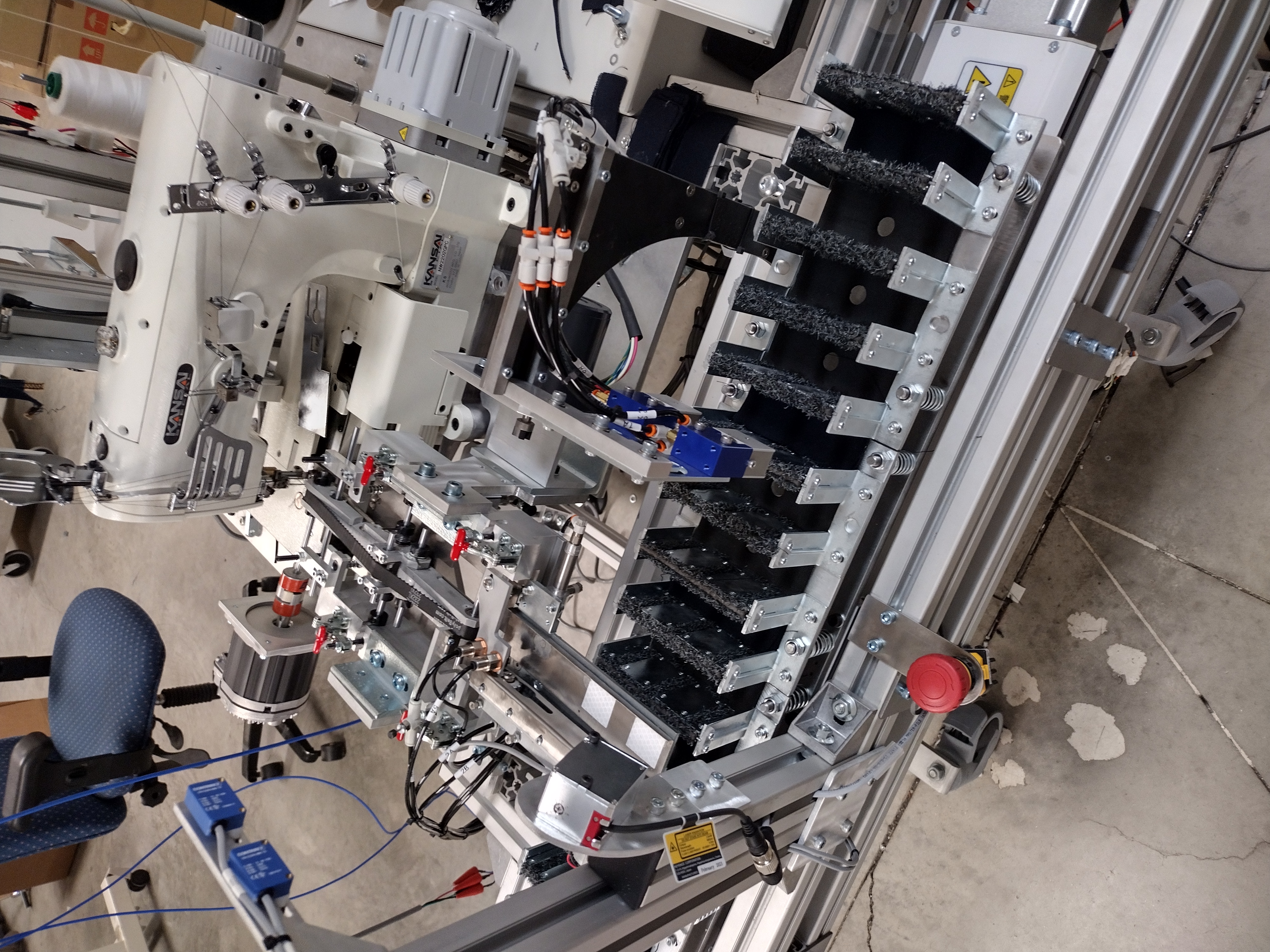
Pick and Place Subsystem
The subsystem included the following components:
- 3 Servo Motors: Two controlled the fabric picker, while one indexed the tray holding the fabric.
- Laser Sensor: Measured the depth the picker needed to reach inside the tray and detected when the tray was empty, triggering an index.
- Proximity Sensors: Calibrated the starting (home) position for the three servo systems.
- Photoelectric Sensors: Detected the presence of fabric at the placement point.
- Limit Switches: Provided safety stops for the servo systems to prevent over-travel.
Here are design iterations of testing different fabric pickers:
The most reliable and cost-effective solution was an off-the-shelf picker:
The picker grabs fabric one piece at a time using multiple needles and can be adjusted to accommodate different fabric types.
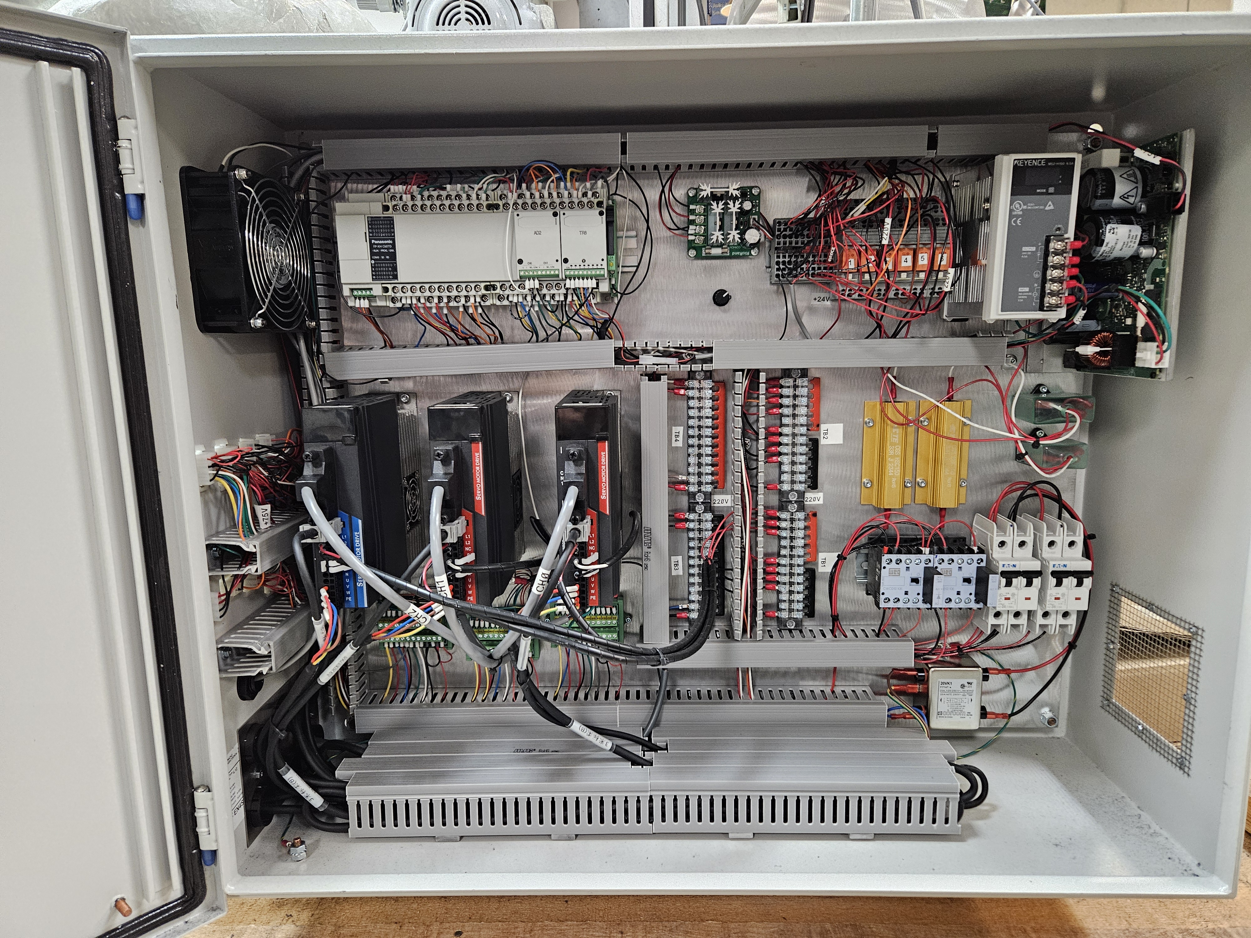
Electrical and Control System
Custom Electrical Control Panel:
- Designed all internal/external wiring and layout
- Integrated sensors, servos, pneumatic solenoids
- Connected to main PLC (FP-XH C60TD)
Control Panel (Inside View)
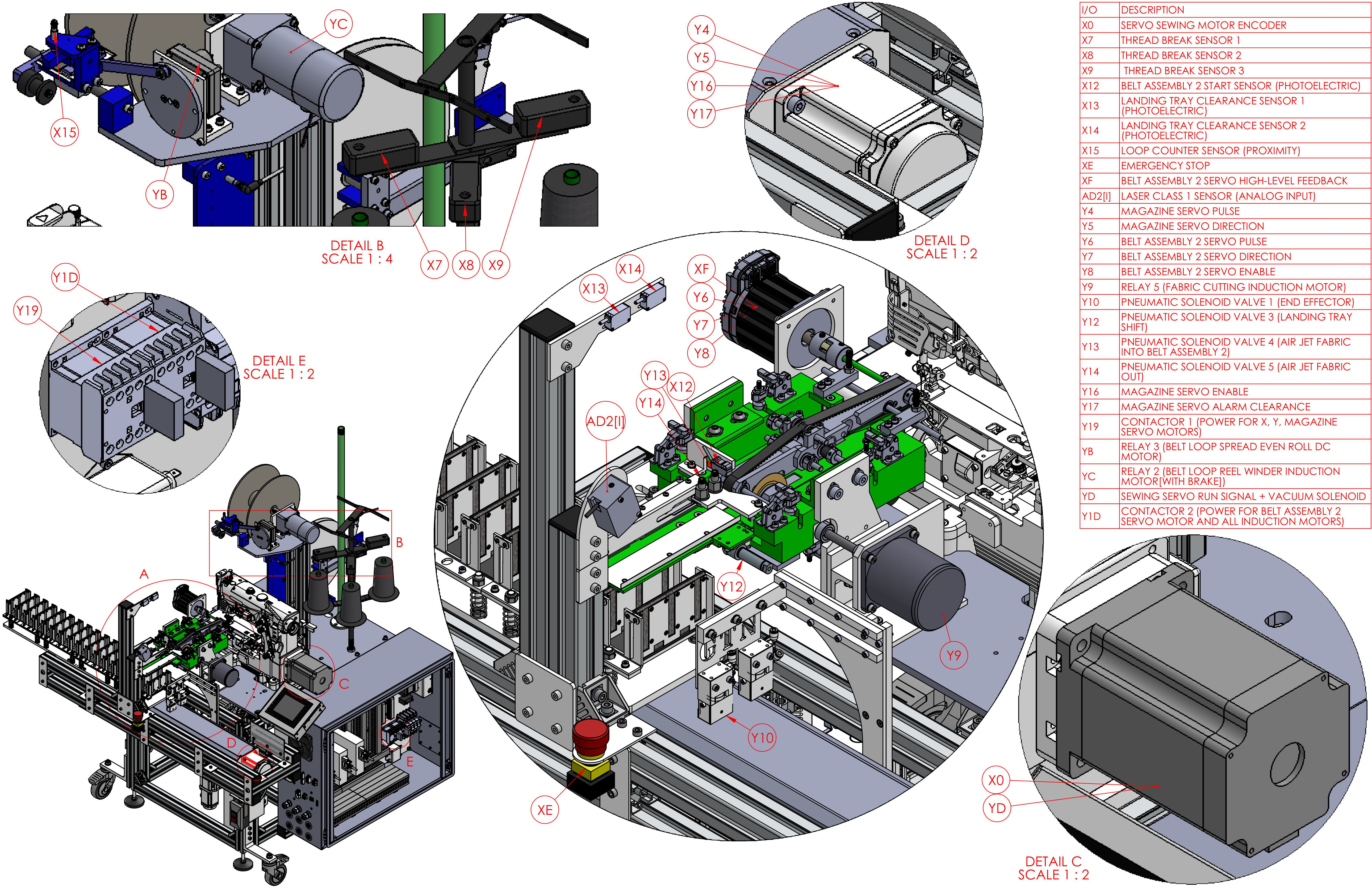
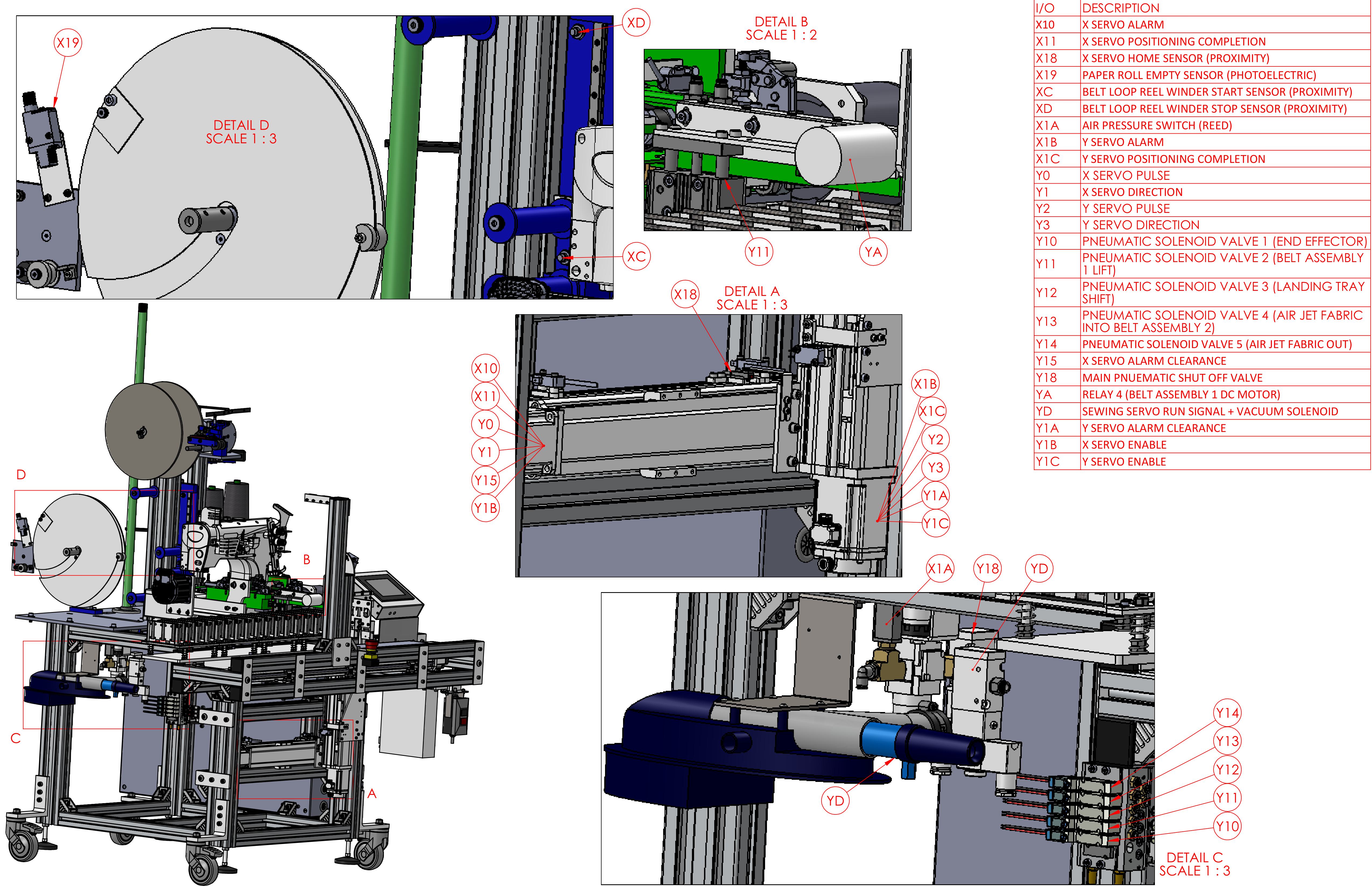
I/O Mapping and Labeling
These annotated diagrams correspond to the PLC wiring and illustrate the physical layout of the machine’s sensors and actuators:
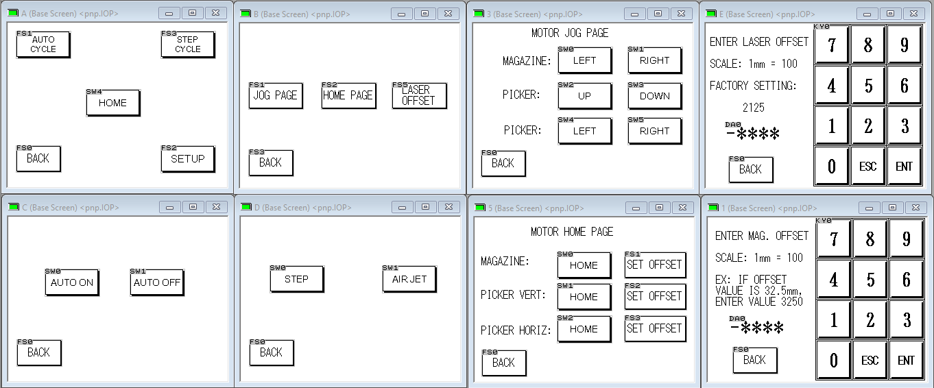
HMI Interface
The system uses a Panasonic GT05 programmable display. These screens show the interface I set up to control and fine-tune the pick-and-place subsystem, including motor homing, jogging, and offset adjustments.
PLC Ladder Logic
The ladder logic program for the pick-and-place subsystem shows the automated and step-by-step testing routines, integrated with the HMI.